Appendix A - Shape File Format
Overview Of The Shape File
The purpose of the shape file is to define how symbols and arrows are drawn. Chartist does not have any self-contained shape definitions; they are all defined in the shape file. One of the properties of a symbol in a chart is its shape. This property is a reference to one of the shapes in the shape file. Each shape in a shape file is uniquely identified by a character string whose length must be less than 16 characters. These names appear in the Choose Symbol Shape dialog in the list box.
When Chartist draws a specific symbol or arrow, it looks up the shape in the shape file, which has been processed and loaded into memory, and retrieves the drawing instructions for that shape. It scales a symbol as defined by height and width properties of the symbol, and draws it, including any text or bitmap that may be part of the symbol. It scales an arrow as defined by the arrow length property for the line.
Thus the shape file is a "keystone" data structure for Chartist. Chartist cannot operate without a proper shape file loaded into memory.
Layout Of The Shape File
The shape file is a plain ASCII (7-bit) text file that is processed by Chartist as it is loaded. Chartist assumes that the shape file is properly constructed, and makes no attempt to check any syntax or semantics of the file.
The general layout of a shape file is:
| Comments | Any commentary information deemed helpful. All comments should precede any shape definitions. Comment lines should start with a semicolon character (;). |
| Shapes | The shape definitions. Each shape definition should follow the format defined below for shapes. |
| Arrows | The arrow definitions. Each definition should follow the format defined below for arrows. |
Shape File Coordinate System
The shape file is based on a center-aligned, unit-less coordinate system. The points in this system are expressed as percentages of the current symbol€™s actual dimensions. The horizontal (x) dimension is positive right, and the vertical dimension (y) is positive down. See the Figure 1 below. Dimensions are processed to signed 8-bit quantities, meaning that they can have have a range of -128 to +127 units.
The 100% Rectangle illustrates the coordinate points of the corners of a shape that would completely fill the actual dimensions of a symbol. The extent of this rectangle is 100 units in both dimensions, and the shape is centered within the boundary of the actual symbol area.
While the 100% Rectangle appears square in this figure, its actual aspect ratio depends upon the current real dimensions of the symbol.
For arrows, the end point of the line is at point (0,0), and the orientation of the line is horizontal, from left to right. Arrow dimensions are determined by their actual length, and shape file entries are all scaled to the arrow length property for the line.
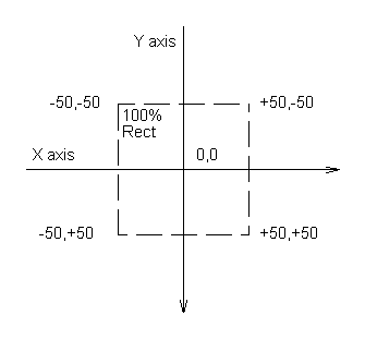
Figure 1
Shape File Coordinate System
Shape Definition Format
The shape definition format is as follows:
| Start Delimiter | $ - All symbol definitions begin with a dollar sign followed immediately by the shape name (with no intervening spaces). |
| Shape Name | A unique printable ASCII character string of less than 16 characters with no embedded commas, or spaces. Quotation marks do not override these restrictions. Terminated with a Field Delimiter. |
| Field Delimiter | Comma, space or end of line. |
| Drawing Instructions | A string of Field Delimited signed numbers as defined below. Terminated with a Field Delimiter. |
| Text Box | The left, top, right, bottom coordinates of a box bounding the text entry area of the symbol. Coordinates are separated by Field Delimiters. Terminated with a Field Delimiter. |
| Bounding Box | The left, top, right, bottom coordinates of a box bounding the total extent ot the shape. Coordinates are separated by Field Delimiters. Terminated with a Field Delimiter. |
Arrow Definition Format
The arrow definition format is as follows:
| Start Delimiter | @ - All arrow definitions begin with an "at" sign followed immediately by the arrow name (with no intervening spaces) |
| Shape Name | A unique printable ASCII character string of less than 16 characters with no embedded commas, or spaces. Quotation marks do not override these restrictions. Terminated with a Field Delimiter. |
| Field Delimiter | Comma, space or end of line. |
| Drawing Instructions | A string of Field Delimited signed numbers as defined below. Terminated with a Field Delimiter. For arrows, the only permitted drawing instructions are Border Brush, Background Brush, Polygon, Line, Ellipse, and Arc. |
Drawing Instructions
Drawing instructions comprise a list of commands and parameters in the form of signed numbers. These signed numbers are separated by Field Delimiters. At the end of the drawing instructions is a Terminating Flag. The total length of a drawing instruction string must be 64 items or less, including the Terminating Flag.
| Terminating Flag | 32767 - The drawing instructions are terminated with this number as the last number in the string. |
The commands themselves have a varying number of parameters depending on the command and the context of the command. The commands are listed and described below. All commands are entered as numeric codes, not as symbolic constants.
Rectangle
Draws a rectangle using the symbol€™s border pen (color and style) and fills that rectangle with the current brush
Code: 1,
Parameters: Left, Top, Right, Bottom, (Shape coordinates,
see above)
Polygon
Draws a polygon using the symbol€™s border pen (color and style) and fills that polygon with the current brush (color). Note that while the maximum number of vertices for this command is 32, the maximum number of items in an instruction string cannot exceed 64. Thus the most complex polygon possible in an actual instruction string would have a most, 30 vertices (30 vertices requires 60 items, plus 2 items for the command code and Nvert, plus 1 more item for the Terminating Flag, for a total of 63 items).
Code: 2,
Parameters: Nvert, (Number of vertices, max
32)
Xv1, Yv1, (Vertex 1)
Xv2, Yv2, (Vertex 2)
... (etc.)
XvNvert, YvNvert, (Final Vertex)
Ellipse
Draws an ellipse using the symbol€™s
border pen (color and style) and fills that ellipse with the
current brush (color).
Code: 3,
Parameters Left, Top, Right, Bottom, (Bounding rect of
ellipse)
Line
Draws a multiple segment line using the
symbol€™s border pen (color and style), If
no solid shape has been drawn in the instruction string to
this point, the Bounding Box of the shape is filled with the
current brush prior to executing this command. Note that the
maximum number of vertices is 32. However, the actual limit
in an instruction string is lower, see Polygon above.
Code: 17,
Parameters: Nvert, (Number of vertices, max
32)
Xv1, Yv1, (Vertex 1)
Xv2, Yv2, (Vertex 2)
... (etc.)
XvNvert, YvNvert, (Final Vertex)
Arc
Draws an elliptical arc using the
symbol€™s border pen (color and style), If
no solid shape has been drawn in the instruction string to
this point, the Bounding Box of the shape is filled with the
current brush prior to executing this command.
Code: 18,
Parameters: Left, Top, Right, Bottom, (Bounding rect of
arc)
Xstart, Ystart, (Start point of arc)
Xend, Yend, (End point of arc)
Round Rectangle
Draws a rectangle with elliptical corners using the
symbol€™s border pen (color and style) and
fills that rectangle with the current brush (color).
Code: 11,
Parameters: Left, Top, Right, Bottom, (Extent of
rectangle)
Width, (Width of ellipse for corner)
Height, (Height of ellipse for corner)
Border Brush
Selects the border brush as the current brush. Causes
subsequent solid shapes in the instruction string to be
filled with a color that matches the border color for the
symbol, as opposed to the background color for the symbol
(the default on starting the string).
Code: 19,
Parameters: [None]
Background Brush
Selects the background brush as the current brush. Causes
subsequent solid shapes in the instruction string to be
filled with the background color for the symbol. Typically
used in a string to reset to the background color after
drawing something filled with the border color.
Code: 5,
Parameters: [None]
Region Commands
In Windows, a region is a graphical data type that may have calculations performed on it, or it may be filled in with a color or pattern. Chartist uses regions to help create complex solid shapes. This means shapes that have combined straight and curved borders and can be filled in with a color. In the current release, lines will route to the actual border of a solid shape, rather than just to the bounding rectangle. Thus, regions provide a more advanced shape definition capability. In the LOGIC.SHP shape file, look at the definition of the Or shape for a strong example of the use of regions.
There are four "scratch" regions that may be used in the process of creating a shape. They are numbered from 0 to 3. All of the region commands refer to one or more of these numbered scratch regions.
ElliRegion
This command creates an elliptical region.
Code 4,
Parameters: Rgn, (The region number (0-3) to use)
Top,Left, Right,Bottom, (Bounding rect of ellipse)
RectRegion
This command creates a rectangular region.
Code 6,
Parameters: Rgn, (The region number (0-3) to use)
Top,Left, Right,Bottom, (Shape coordinates)
PolyRegion
This command creates a polygon region.
Code 8,
Parameters: Rgn, (The region number (0-3) to use)
Nvert, (The number of vertices, max 32)
Xv1,Yv1, (Vertex 1)
Xv2,Yv2,
...
XvNvert,YvNvert, (Final Vertex)
CombineRegion
This command combines two regions, according to the operation parameter provided.
Code 9,
Parameters: DestRgn, (The region number for result)
SrcRgn1, (First source region)
SrcRgn2, (Second source region)
Operation, (Operation parameter, see below)
Operations
AND: 1 (Result is overlap of src's)
COPY: 2 (Result is copy of src 1)
DIFF: 3 (Result is src 1 not in src 2)
OR: 4 (Result is union of src's)
XOR: 5 (Result is non overlap union)
FillRegion
This command fills the selected region with the current brush. Note that no border is drawn around the region. The border must be drawn with line or arc commands, separately.
Code 10,
Parameters Rgn (Region number to use)
Examples
The following are annotated excerpts of shape definitions from the standard Chartist shape file as of version 1.03.
The standard Rect shape is defined as follows:
$Rect
2, 4,-50,-50, 50,-50, 50, 50,-50, 50, 32767
-50,-50, 50, 50
-50,-50, 50, 50
The shape name is preceded by the start delimiter ($). It is on a line by itself for readability.
The drawing instructions follow next. This is a polygon shape with four vertices. The Polygon command is used here instead of the Rectangle command to compensate for a characterstic of Windows GDI rectangles. Windows rectangles do not include the bottom and right points, this leaving the rectangle 1 pixel (or logical unit) smaller than actually intended in each dimension. Since the Rect is the most often used shape, the Ploygon command was used, to get that last pixel included, for aesthetics.
Next come the Text Box and Bounding Box Dimensions, to complete the definition.
The Rect-Shad is a more complex shape that illustrates the use of brush selection and combined solid shapes.
$Rect-Shad
19
2, 6, 50,-50, 56,-44, 56, 56
-44, 56,-50, 50, 50, 50
5
1,-50,-50, 50, 50
32767
-50,-50, 50, 50
-50,-50, 56, 56
The first drawing command selects the border brush. This allows the shaded portion of the shape to track the symbol€™s selected border color. Next comes the rather complex polygon that forms the shaded portion. This is followed by the re-selection of the background brush and the rectangle outlining the shape. The actual rectangle command was used here, since the bottom and right sides of the symbol have already been dealt with by the shaded portion.
Note that the bounding box is over scaled on the right and bottom. This is done do enclose the shaded portion of the symbol. The dimensions of this shape were set up so that it would have the same internal area as the plain rectangle.
The Docu (printed output) symbol is shown to illustrate the drawing of a complex shape approximating curves with straight lines. It is important to note that this technique must be used to draw compound shapes that appear to have curved outlines if you expect them to be filled with color properly. You cannot make a solid shape from lines and arcs. Those shapes will be filled with a rectangular area of background color.
$Docu
2,12,-50, 38,-50,-50, 50,-50, 50, 38, 44, 31, 31, 25
19, 25, 6, 31, -6, 44,-19, 50,-31, 50,-44, 44
32767
-50,-50, 50, 25
-50,-50, 50, 50
The 12 vertex polygon defines the entire shape outline. Notice that the text box is not centered vertically in the shape.
The Clsd-2:1-F arrow shows an example of an arrow type. This arrow is the standard filled triangle with a 2:1 aspect ratio
@Clsd-2:1-F
19
2, 3,-100,-25, 0, 0,-100, 25, 32767
Notice that the arrow extends from -100 to 0 in the X direction.
Procedure For Making Your Own Shapes
First make a back up copy of the default shape file, and keep it safe. You cannot run Chartist without a good shape file. You might want to set the read only attribute of that file with DOS.
You may use the default shape file as a basis for your own shape file. You must however leave the copyright notice intact. You may add your own copyright notice in the comments section claiming copyright of the added material.
Use an plain text editor, such as Notepad or whatever is convenient. You should stay with the ASCII-7 printing character set however for all text in the file. You should only save the file in standard ASCII format, never in any proprietary word processor file format.
Start with simple experiments and build on that. For example you might want to try changing slightly (and re-naming) one of the standard shape definitions.
When you load a new shape file, Chartist "remembers" the path to that file in the CHARTIST.INI (CHARTST2.INI for Chartist-2) file which is located in your WINDOWS directory. This means that if you load a shape file that does not work, Chartist will keep using it until you load a new one. You can get Chartist to revert to the default shape file by either loading it explicitly from the main menu, or by deleting the CHARTIST.INI file, or by deleting the line in that file that begins with "shapefile=". This assumes that the default shape file is located in the same directory as the Chartist application.